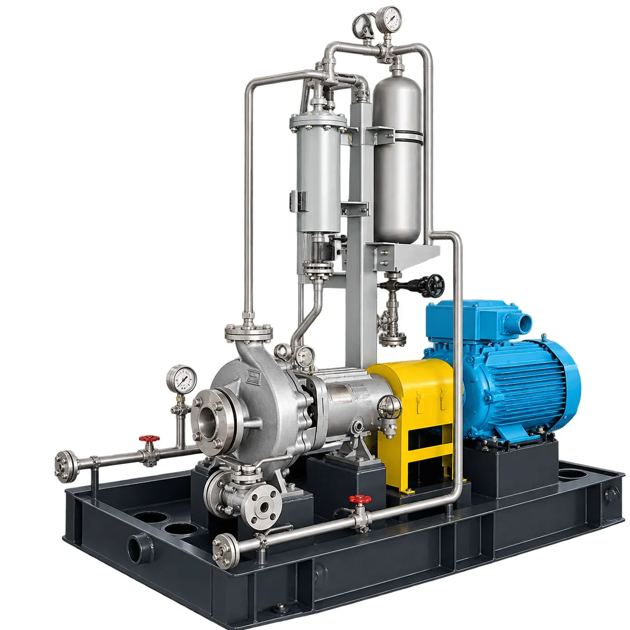
API 682 Plan 53A and 53B Chemical Pump System
Product Information
Seal arrangement:
Dual Pressurized Mechanical Seal
Pressure source:
External nitrogen supply
Gas and liquid contact:
Direct contact in reservoir
Pressure level:
Above seal-chamber pressure
Materials:
SS304, SS316L, or project-specific alloy


API 682 Plan 53A and Plan 53B systems supply clean, pressurized barrier fluid to dual mechanical seals. The barrier pressure remains above the pump seal-chamber pressure. Therefore, the process liquid cannot move across the inboard seal toward the atmosphere during normal operation.
These systems are suitable for toxic, flammable, corrosive, abrasive, or polymerizing liquids. They can be installed on ZA, ZE, IH, and other horizontal chemical process pumps.
Jingjiang Liutong Pump Industry Co., Ltd. can supply the pump, dual mechanical seal, barrier-fluid system, motor, coupling, instruments, piping, and baseplate as one integrated package.
Representative System Configuration
| Item | Plan 53A | Plan 53B |
| Seal arrangement | Dual pressurized mechanical seal | Dual pressurized mechanical seal |
| Pressure source | External nitrogen supply | Nitrogen-precharged bladder accumulator |
| Gas and liquid contact | Direct contact in reservoir | Separated by bladder |
| Barrier-fluid circulation | Seal pumping ring | Seal pumping ring |
| Cooling method | Reservoir cooling coil or external cooler | Air- or water-cooled heat exchanger |
| Pressure level | Above seal-chamber pressure | Above seal-chamber pressure |
| Typical service | Low- to moderate-pressure duties | Higher-pressure or remote duties |
| Monitoring | Pressure, level, and temperature | Pressure, temperature, and accumulator status |
| Installation | Pump-mounted or skid-mounted | Pump-mounted or skid-mounted |
| Materials | SS304, SS316L, or project-specific alloy | SS304, SS316L, or project-specific alloy |
System pressure, reservoir volume, bladder size, cooler area, piping size, and alarm settings are selected for each application.
How the Pressurized Barrier System Works
The space between the inboard and outboard mechanical seals is filled with clean barrier fluid. A pumping ring inside the seal moves this fluid through a closed piping loop while the pump shaft rotates.
The barrier fluid lubricates the seal faces and removes heat. It then passes through a reservoir or cooler before returning to the seal.
Since the barrier pressure is higher than the seal-chamber pressure, a small amount of compatible barrier fluid may enter the process. However, the process medium is prevented from reaching the atmosphere while the required pressure difference is maintained.
API Plan 53A
Plan 53A uses an external gas supply, normally nitrogen, to pressurize a barrier-fluid reservoir. The gas acts directly on the liquid inside the vessel.
A pumping ring circulates the barrier fluid during operation. Meanwhile, a cooling coil or external cooler removes seal-generated heat. Thermosyphon circulation may continue after the pump stops.
Plan 53A offers several benefits:
- Simple and proven system design
- Easy visual level inspection
- Low routine maintenance
- Clean lubrication for both seals
- Reservoir cooling options
- Pressure and level alarm functions
- Compact installation beside the pump
- Lower system complexity than many high-pressure plans
Plan 53A needs a stable nitrogen supply. In addition, the barrier fluid must be compatible with the process because limited barrier-fluid leakage into the pump is expected.
API Plan 53B
Plan 53B uses a bladder accumulator to maintain barrier-fluid pressure. Pressurized nitrogen stays inside the bladder, while the barrier fluid remains outside it. Therefore, the gas and liquid do not come into direct contact.
The separate gas chamber reduces the risk of nitrogen dissolving in the barrier fluid. It also removes the need for a continuous plant nitrogen supply after the accumulator has been correctly charged.
Plan 53B is often selected for:
- Higher seal-chamber pressures
- Harsh process conditions
- Remote installation sites
- Sites without a stable nitrogen network
- High-vapor-pressure liquids
- Light hydrocarbons
- Toxic or flammable chemicals
- Polymerizing process liquids
Because the available barrier-fluid volume is limited, cooler performance and accumulator sizing are important. The system pressure must also be monitored throughout operation.
Main System Components
A complete Plan 53A or Plan 53B chemical pump package may include:
- ZA, ZE, or IH chemical process pump
- Dual pressurized cartridge seal
- Barrier-fluid reservoir or bladder accumulator
- Seal pumping ring
- Water-cooled or air-cooled heat exchanger
- Pressure gauge and pressure transmitter
- Level gauge or level switch
- Temperature gauge or transmitter
- Low-pressure and low-level alarm sensors
- Stainless steel tubing and fittings
- Isolation, filling, vent, and drain valves
- Electric motor and coupling guard
- Common baseplate and drain collection tray
The exact instrument type can match the customer’s plant control system.
Compatible Chemical Process Pumps
The seal support package can be configured for several pump families.
ZA chemical process pumps are suitable for general chemical, petrochemical, acid, alkali, solvent, and industrial process duties.
ZE process pumps are used for more demanding refinery, petrochemical, high-temperature, or high-pressure services.
IH chemical pumps provide a practical option for transferring clean, corrosive liquids in chemical production, pharmaceutical plants, surface treatment, and water treatment.
Pump flow, head, temperature, pressure, material, and motor power depend on the selected pump model. Therefore, the barrier system must be engineered together with the pump and mechanical seal.
Suitable Process Media
Plan 53A and Plan 53B packages can be used for:
- Toxic chemical liquids
- Flammable solvents
- Light hydrocarbons
- Acids and alkalis
- Heat-transfer fluids
- High-vapor-pressure products
- Polymer and resin liquids
- Crystallizing chemicals
- Dirty or abrasive process media
- Liquids that cannot contact the atmosphere
Barrier-fluid compatibility must be confirmed before final selection. It should not cause an unsafe reaction, damage product quality, or attack the seal materials.
Integrated Skid-Mounted Supply
The units shown in the photographs combine the chemical pump and seal support equipment on one fabricated baseplate. This arrangement simplifies site installation and reduces field pipework.
The manufacturer can complete:
- Pump and motor alignment
- Seal support piping
- Reservoir or accumulator mounting
- Cooler installation
- Instrument and alarm fitting
- Pressure testing
- Rotation inspection
- Baseplate fabrication
- Protective coating
- Export packing
The system can also be supplied with customer-specified flange standards, motor voltage, hazardous-area motors, instrumentation brands, and electrical interfaces.
Selection Information
Please provide the following data for an accurate proposal:
- Pump type and model
- Required flow and head
- Process liquid and concentration
- Operating and maximum temperature
- Density and viscosity
- Vapor pressure
- Solid or polymer content
- Suction and discharge pressure
- Normal and maximum seal-chamber pressure
- Mechanical seal size and arrangement
- Available nitrogen pressure
- Cooling-water temperature and flow
- Hazardous-area classification
- Instrument signal requirements
- Required alarm and shutdown settings
This information helps determine whether Plan 53A or Plan 53B is the better choice.
Installation and Operation
Install the support system close to the mechanical seal. Keep the piping short, clean, and free from trapped air. The return line should rise toward the reservoir or cooler where required.
Before starting the pump:
- Fill the system with approved barrier fluid.
- Vent all air from the seal loop.
- Confirm the correct barrier pressure.
- Check the nitrogen or accumulator charge.
- Open all required isolation valves.
- Start the cooling-water supply.
- Test the pressure and level alarms.
- Confirm pumping-ring circulation.
Never operate the pump after losing barrier pressure. Low pressure can allow process liquid to enter the seal system and may result in unsafe leakage.
Manufacturer Engineering Support
Jingjiang Liutong Pump Industry Co., Ltd. provides pump selection, dual-seal matching, seal-plan design, material selection, cooler sizing, instrument configuration, skid assembly, and factory inspection.
Each package can be designed around the customer’s process conditions. In addition, spare seals, bladder accumulators, gauges, transmitters, valves, and barrier-fluid components can be supplied for long-term maintenance.
Frequently Asked Questions
What is the main difference between Plan 53A and Plan 53B?
Plan 53A uses external nitrogen in direct contact with the barrier fluid. Plan 53B uses a bladder to separate the nitrogen from the barrier fluid.
Which system is better for higher pressure?
Plan 53B is generally more suitable because its bladder accumulator can support higher-pressure duties without direct gas-liquid contact.
Can these systems stop chemical leakage?
They prevent process-fluid leakage to the atmosphere while the dual seal and barrier pressure operate correctly.
Does the barrier fluid enter the process?
A small amount may pass across the inboard seal. Therefore, the fluid must be compatible with the process.
Can the complete pump skid be customized?
Yes. Pump model, seal type, vessel volume, pressure rating, cooler, instruments, motor, piping, and baseplate can be configured for the project.
Request a Plan 53A or Plan 53B System
Send us your pump and seal-chamber data. Our technical team will recommend a complete API 682 Plan 53A or Plan 53B chemical pump package for safe, long-term operation.
Recommended products
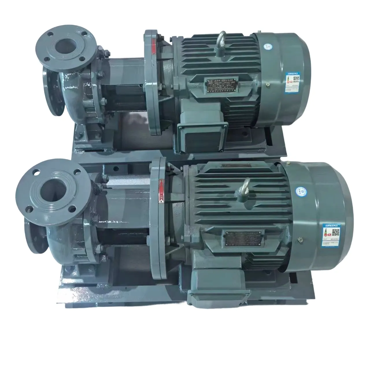
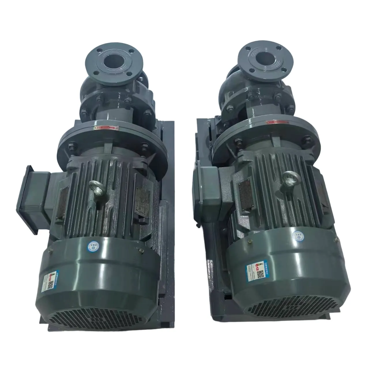
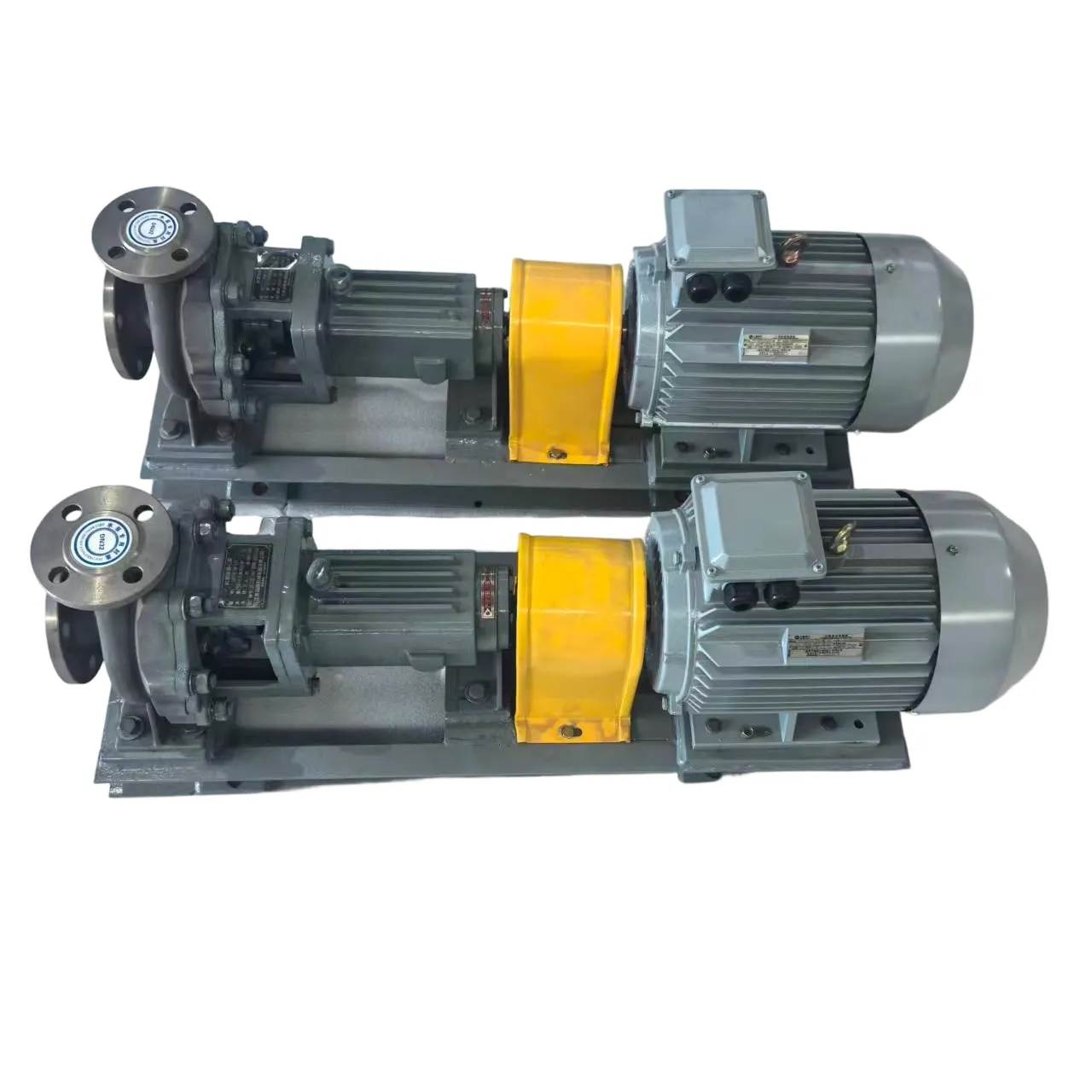
Horizontal Direct-Connect Centrifugal Chemical Pump
Compact horizontal direct-connect centrifugal chemical pump for corrosive liquids, with custom stainless steel materials, seals, motors, and hydraulic sizes.
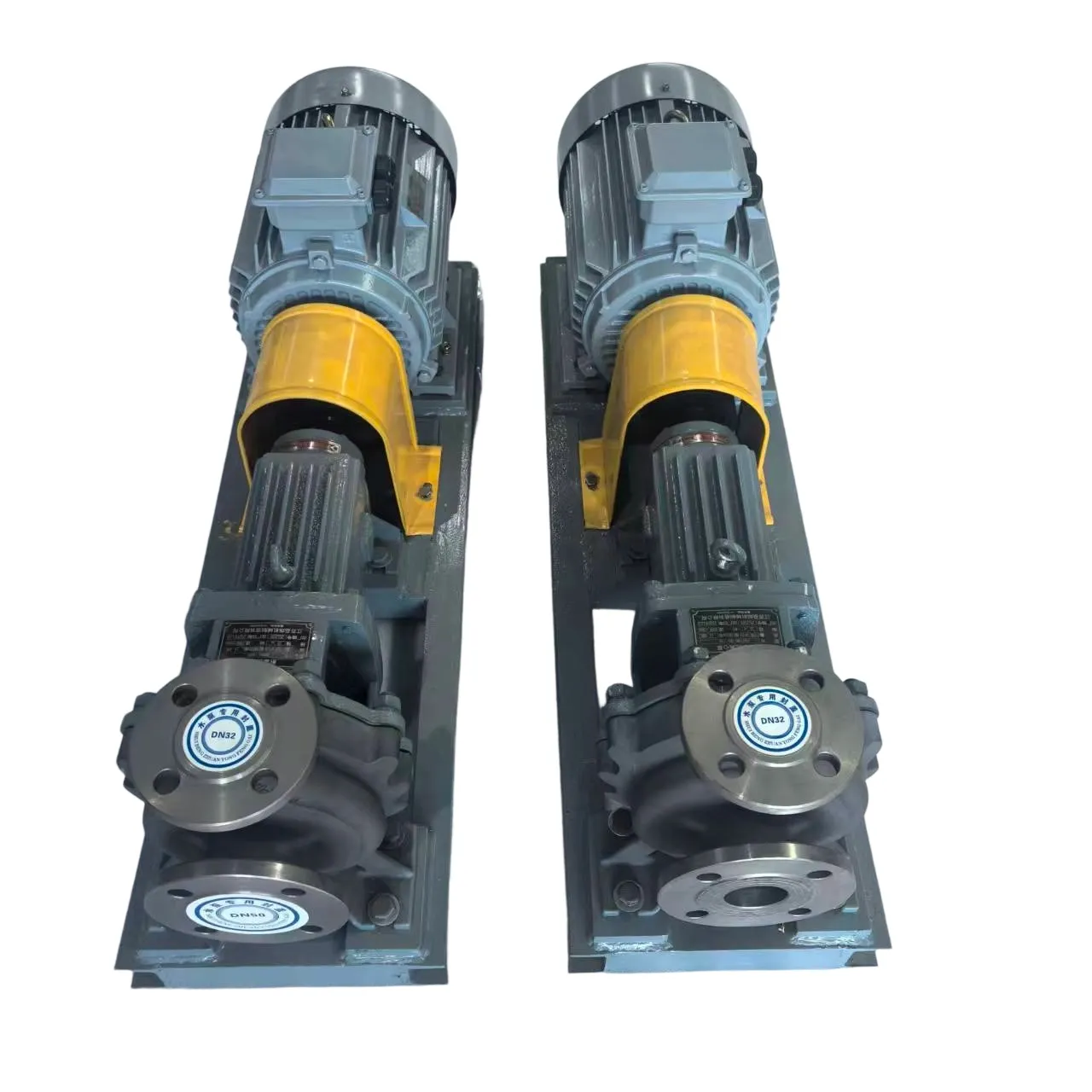
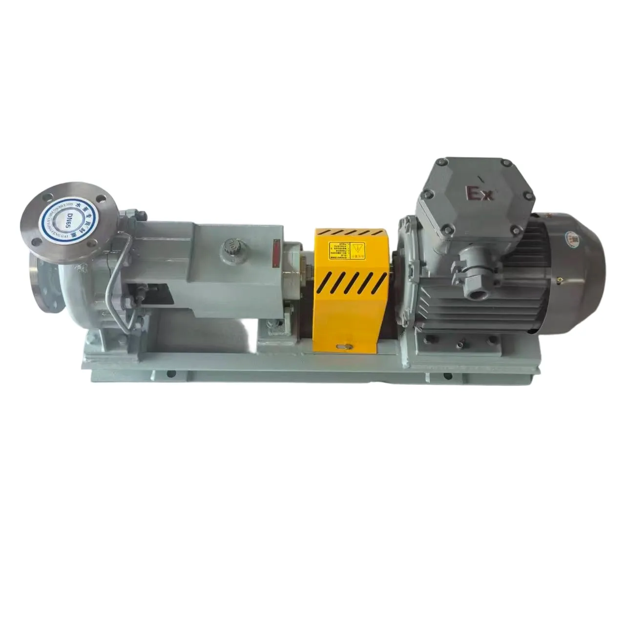
IH Centrifugal Chemical Pumps
IH centrifugal chemical pumps for acids, alkalis, solvents, and industrial process liquids. Available with custom materials, seals, motors, and sizes.
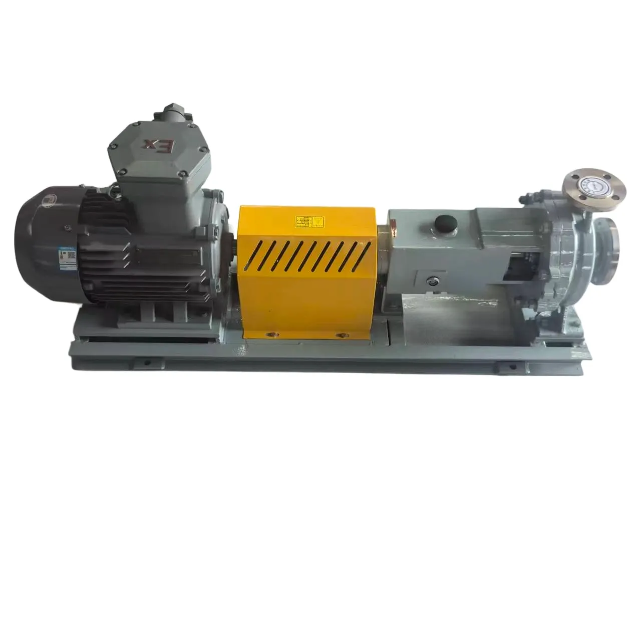
HJ Centrifugal Chemical Pump
HJ centrifugal chemical pump for corrosive, toxic, flammable, and particle-containing liquids. Custom materials, seals, motors, and performance.
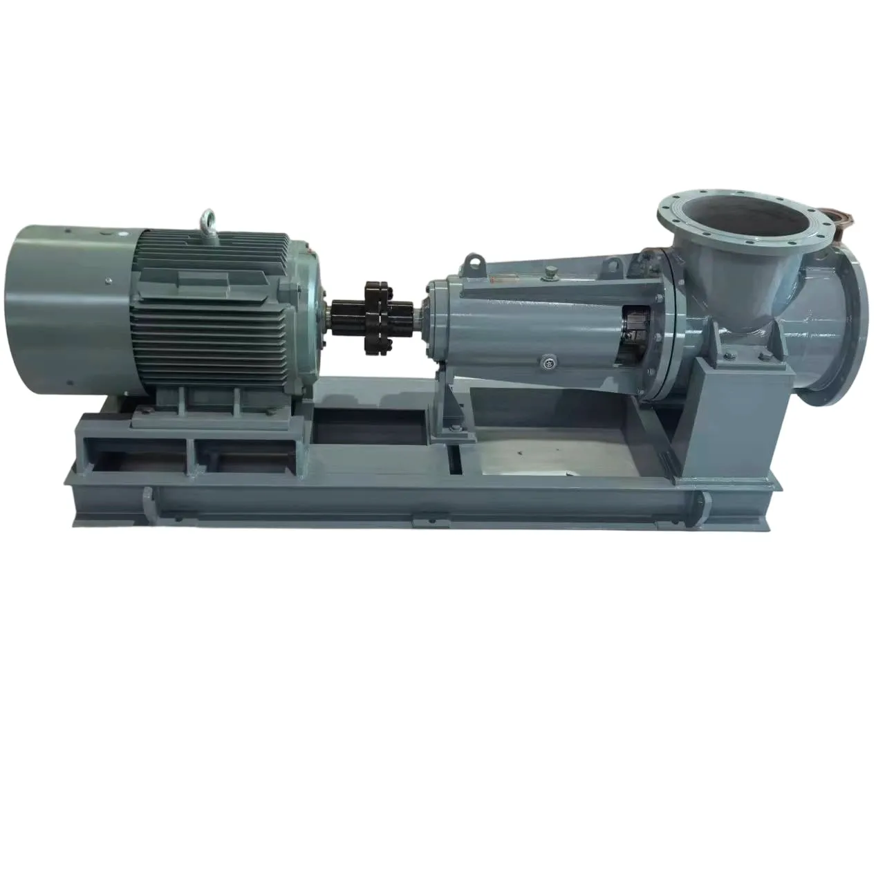
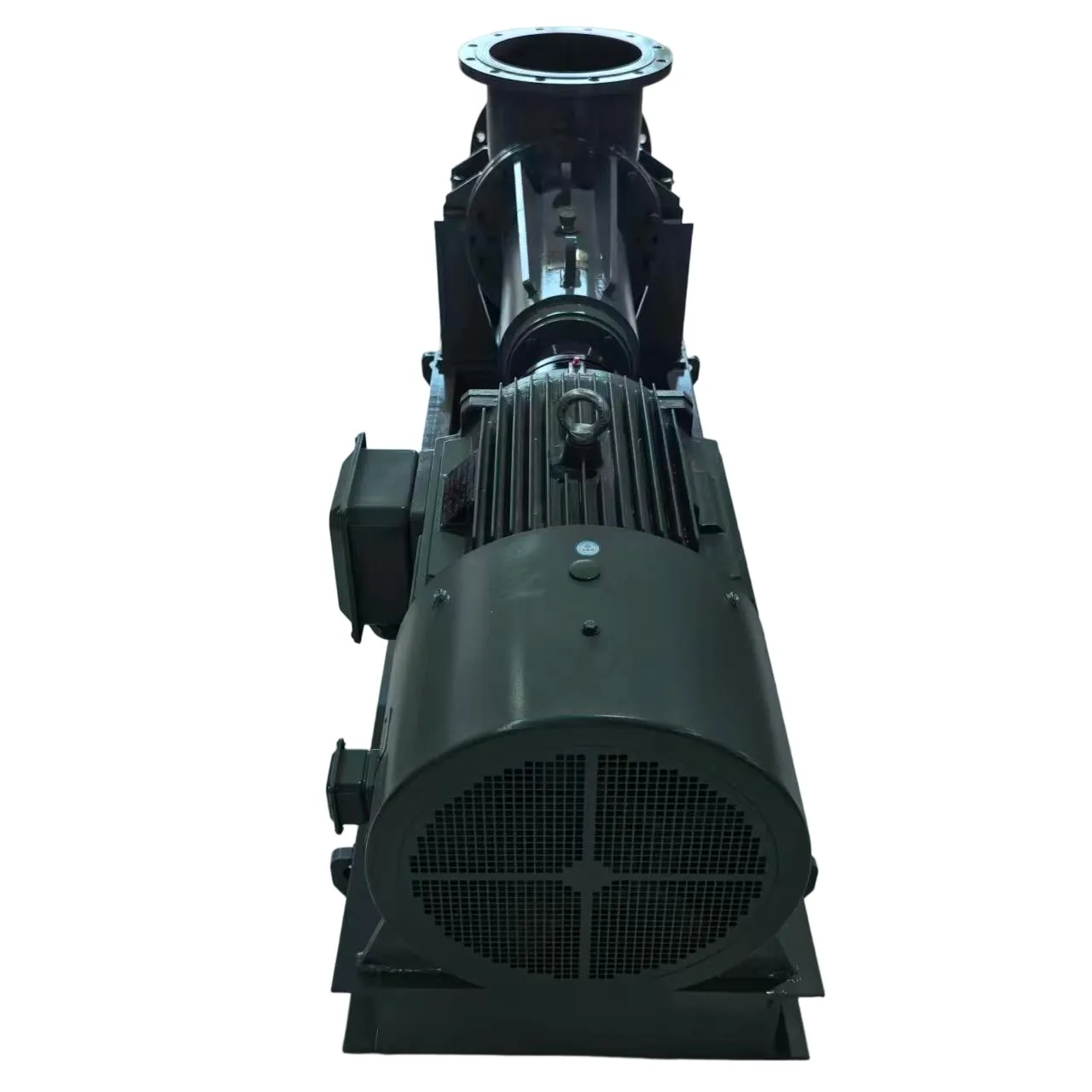
FJX Evaporator Forced-Circulation Axial Flow Pump
FJX evaporator circulation pump delivers 300–12,000 m³/h for evaporation, crystallization, and reactor systems, with adjustable blades and durable seals.


